Conserving a thermopile in UCL Science and Engineering Collections
By Emilia L Kingham, on 24 March 2016
My name is Dae Young Yoo and I am the MSc. Conservation student placement with UCL Museums and Collections. One of my objects that I have been assigned to research and conserve is a thermopile from the Physiology Department.
Object Description:
According to the UCL object database, it is presumed that two physiologists, Archibald Vivaina Hill (1886 – 1977) and Te-Pei Feng (1907 – 1995) made the thermopile in 1933. The thermopile was used for measuring the heat-production in sartorius muscle.
A function of the thermopile is the conversion of thermal energy into electrical energy. Thermopiles are still widely utilised in many areas such as in the medical profession for the measurement of body temperature, heat sensors and gas burner safety controls (Wikipedia 2016).
Before the thermopile was invented, it was impossible to accurately measure the heat production of muscle (Katch 1997). Hill and co-workers devised the instrument and used it for their historic experiments.
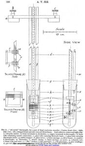
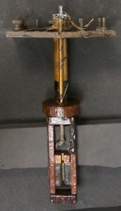
The object is made of various materials (vulcanite, Bakelite, brass, copper and silver) (Hill 1928, 126). The location of each material is shown in the drawing (see Fig 1). Several other materials (Shellac, paraffin wax and beeswax) were also applied on the object. The shape of the object is slight different but is similar to the thermopile introduced at the proceedings of the Royal Society of London in 1929 (see Fig 2). The design of the thermopile in 1929 was devised to improve the previous thermopile shown in 1926 (see Fig1 and 2).
Condition
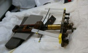
The flow of the coating can be seen on the surface of the object. The coating made the surface of the object bumpy (see Fig 3). It is thought that the surface of the object was coated with Bakelite varnish for insulation. To complete the insulation, the whole instrument was then dipped in molten paraffin wax (melting point 40°C), mixed with white beeswax. In addition, the paraffin wax over Bakelite protects the thermopile from moisture (Hill 1928, 129).

Figure 3. The surface of the rectangular piece is bumpy and irregular. The other area on the surface shows the same.
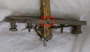
As seen in Figure 3, the rectangular pieces have separated. When the pieces are aligned together, the gap between them is filled with yellow unknown material (see Fig 4). This filling material fits well, with no gaps to fill in order to create a good join.

Figure 5 shows a locally corroded screw and metal tube. The colour of corrosion products is greenish and circular in shape.
Figure 5. Left: one of corroded screws on the long rectangular piece, Right: corroded metal tube
Treatment
The dust on the object was removed with a brush. The existing filling material between the rectangular pieces was not removed. Although the yellow filling material can be removed with a scalpel, it is solid and difficult to remove. Also, using a scalpel to clean the fill material risked damaging the surface.
The corrosion product on the metal tube was removed with calcium carbonate in IMS rubbing with rolled cotton wools at the tip of toothpick. Loosely attached corrosion products were carefully removed with a scalpel.
The separated long rectangular pieces were put together with HMG Paraloid B72 adhesive. Clamps were used to fix the pieces during adhesive curing time (See Fig 6).
Treatment is in progress now. After finishing treatment, it will be packaged in a custom-made box. It is expected that it could be used for teaching material in the Physiology department at UCL.
References
Downing, A. C. & Hill, A. V., 1929. A New Thermopile for the Measurement of Nerve Heat-Production. Proceedings of the Royal Society of London B: Biological Sciences, 105, 147-152.
Hill, A. V., 1928. Myothermic apparatus. Proceedings of the Royal Society of London B: Biological Sciences, 103, 117-137.
Katch, F. I., 1997. Archibald Vivian Hill (1886-1977). Retrieved on 1st March 2016 from World Wide Web: http://www.sportsci.org/news/history/hill/hill.html
Wikipedia, 2016. Thermopile. Retrieved on 1st March 2016 from World Wide Web: https://en.wikipedia.org/wiki/Thermopile
 Close
Close


